Moment of Inertia Formulas: Quick Guide for Engineers

Understanding moment of inertia formulas is crucial for engineers working in fields like mechanical engineering, civil engineering, and physics. It’s a fundamental concept that helps analyze rotational motion and structural stability. Whether you’re designing a beam, calculating stresses, or optimizing machinery, mastering these formulas can save time and ensure accuracy. This guide breaks down the essential moment of inertia formulas, their applications, and practical tips for engineers.
What is Moment of Inertia?

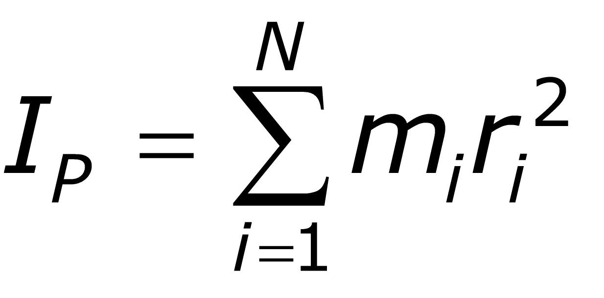
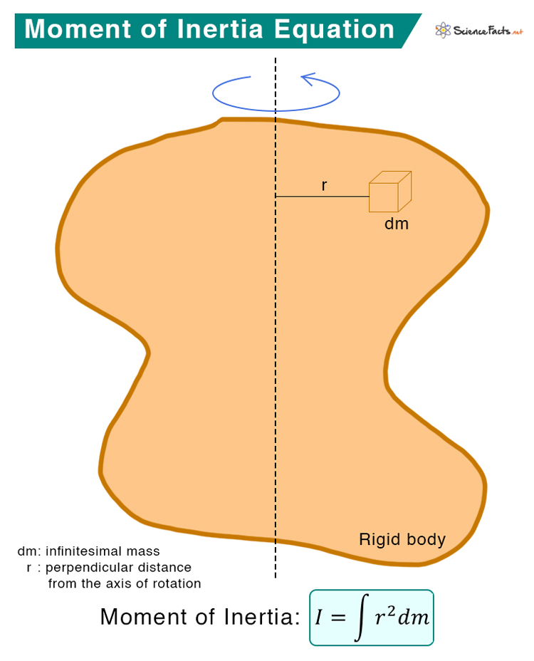
The moment of inertia, often denoted as I, is a measure of an object’s resistance to rotational motion around a specific axis. It depends on the object’s mass distribution and the chosen axis of rotation. Think of it as the rotational equivalent of mass in linear motion.
💡 Note: Moment of inertia is also known as the second moment of area in structural engineering contexts.
Key Moment of Inertia Formulas for Engineers

Below are the most commonly used moment of inertia formulas for various shapes. These are essential for calculations in rotational dynamics and structural analysis.
1. Moment of Inertia for Common Shapes
Here’s a table summarizing formulas for standard geometric shapes:
| Shape | Formula (Axis through Center) |
|---|---|
| Rectangle | I = \frac{1}{12}bh^3 |
| Circle | I = \frac{1}{2} \pi r^4 |
| Triangle | I = \frac{1}{36}bh^3 |
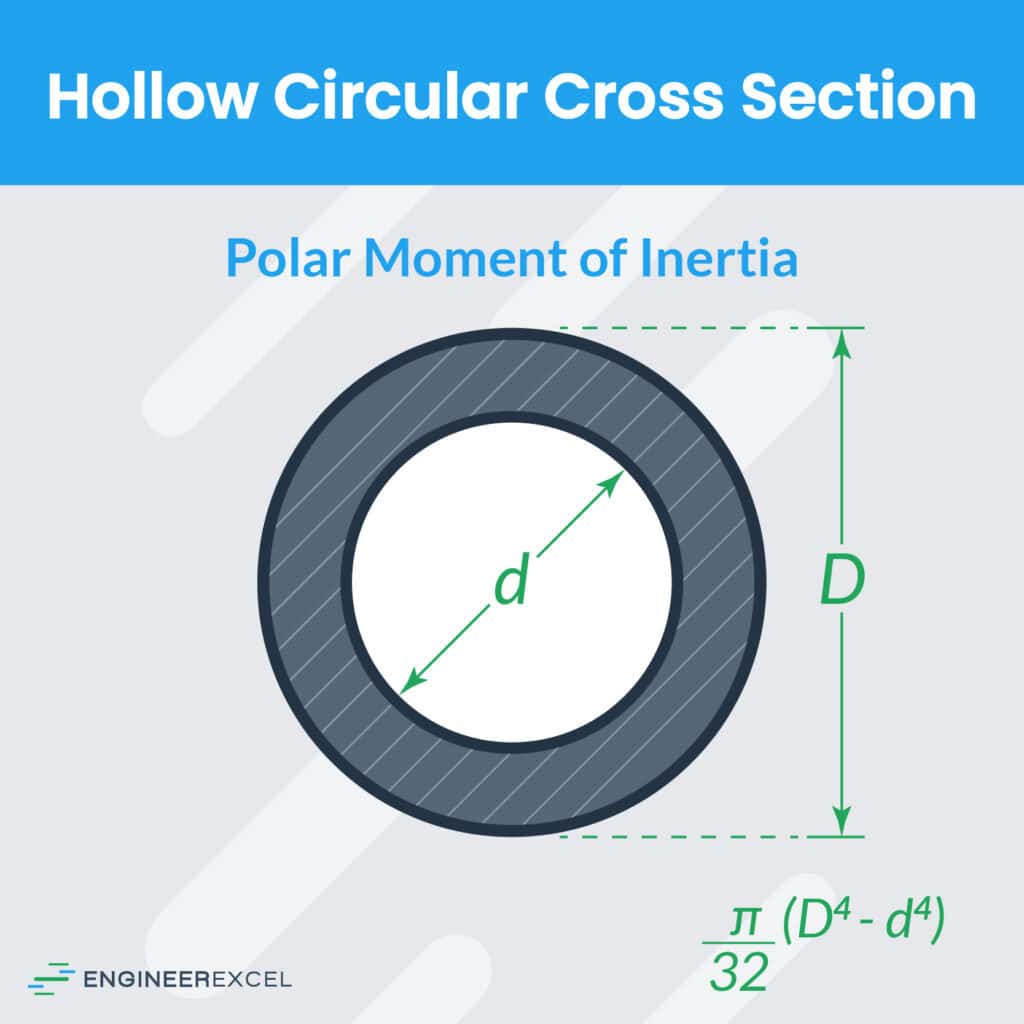
| Hollow Cylinder | I = \frac{1}{2} \pi (R^4 - r^4) |

2. Parallel Axis Theorem
When the axis of rotation is not through the center of mass, use the parallel axis theorem:
[
I = I{\text{cm}} + md^2
]
Where:
- (I{\text{cm}}) = Moment of inertia about the center of mass
- (m) = Mass of the object
- (d) = Distance from the center of mass to the new axis
✨ Note: This theorem is particularly useful for irregular shapes or off-center rotations.
3. Composite Shapes
For complex shapes, break them into simpler components and sum their moments of inertia:
[
I{\text{total}} = \sum I{\text{individual}}
]
Practical Applications of Moment of Inertia

- Structural Engineering: Calculate beam deflection and stress distribution.
- Mechanical Engineering: Design rotating components like flywheels and gears.
- Physics: Analyze rotational kinetic energy and angular momentum.
Quick Checklist for Engineers

- Identify the shape and axis of rotation.
- Use the correct formula for the given shape.
- Apply the parallel axis theorem if needed.
- Double-check units (e.g., (mm^4) or (m^4)).
For engineers looking to streamline their calculations, mastering these moment of inertia formulas is essential. Whether you’re working on a small project or a large-scale design, accuracy starts with the right formulas.
What is the moment of inertia for a rectangular beam?
+The moment of inertia for a rectangular beam about its center is I = \frac{1}{12}bh^3, where b is the width and h is the height.
How does the parallel axis theorem work?
+It allows you to calculate the moment of inertia about a new axis by adding md^2 to the moment of inertia about the center of mass, where m is the mass and d is the distance between the axes.
Why is moment of inertia important in engineering?
+It’s crucial for analyzing rotational motion, structural stability, and stress distribution in engineering designs.
By understanding and applying these moment of inertia formulas, engineers can tackle complex problems with confidence. Whether you’re a student or a seasoned professional, this quick guide ensures you have the tools you need.
Related: moment of inertia calculator, rotational dynamics, structural analysis, engineering formulas.


